Roadway Sides Rock Deformation
ABSTRACT
Combined with the deepening of coal mining, influencing distance and degree of working face advance stress increase gradually. Under deep working face advance stress, roadway deformation quantity could reach 1000-plus mm. We have to affix great importance to the entire demand of the important concept of working face mining on roadway encircling rock and roll stress and motion.
ROADWAY SURROUNDING ROCK GENERAL SITUATION
1252(1) working face can be found on -610 horizontal level, W1 mining area, mining Coal 11-2 mainly, surface elevation +22.3 ~ +24.9 m, working face elevation -642~-720m, to the east of western wing 11-2 coal seam area drop, to the western world of F5 boundary problem, to the north of 1242(1) working face also to the south of -720m coal seam floor contour brand. This working face shows a great coal seam roof-floor "U-shaped" heave from east to western world, coal rock and roll strata event is 180~200??10~18?, coal seam suggest obliquity is 14.5?. Coal 11-2, black bulk and powder, is semi-dark briquette. Generally, coal seam builds up a level of gangue. Incomplete gangue undergoes a phase changeover to false rooftop. Gangue is carbon or mudstone mudstone, 0~0.4m dense, with the average width of 0.2m. Coal seam is 1.5~3.0m dense, with the average width of 2.4m. The coal seam roof-floor conditions are shown in Table 1.
Experimental place is situated at working face roadway with a depth of -642m. Roadway is the gob-side access travelling of small pillars. Anchor wire helping method is used for roadway helping, it could be observed in Fig 1.
- The roadway roof covering adopts seven IV left-hand screw thread metallic ultra high durability pre-tension bolts, with a 5.0m T1 metal strap and 8# rhombus material mesh as put together supporting. Bolt standards is ?22-M24-2800mm, and two Z2360 medium velocity resin cartridges are being used as lengthening anchorage for every single bolt. Bolts are installed with a 800mm distance and 900m row space.
- Roadway low edges utilize four left-hand screw thread material high power pre-tension bolts, with a 2.3m M3 material group, 8# rhombus material mesh as merged supporting. Bolt standards is ?20-M22-2500mm, and one Z2360 medium rate resin cartridges is employed as lengthening anchorage. Bolts are installed with a 700mm distance and 900m row space.
- Roadway high edges utilize six left-hand screw thread material high durability pre-tension bolts, with a 3.0m M3 metallic group, 8# rhombus steel mesh as put together helping. The uppermost bolt (with a 300x300mm large pallet) is installed individually at the roadway shoulder viewpoint with a 200mm depth from the roofing. The other five bolts are installed relating to steel music group holes. Bolt standards is ?20-M22-2500mm, and one Z2360 medium velocity resin cartridges is employed as lengthening anchorage. Bolts are installed with a 700mm distance and 900m row space.
- A couple of high pre-stress anchor craning beam is collocated on the top bolt at every two rows. Anchor cable television holes are assemble on the top midline attributes with a 0.9m distance. The row space of anchor cable connection beam is 1.8m, anchor roofing and cable connection are perpendicular to one another. Steel strand specification is ?17.8x6300mm with a level of 2.2m T2 material group or 16# route steel. Hole space of metal route or music group metallic is 1.8m. Each opening adopts three Z2360 medium velocity resin cartridges as lengthening anchorage. The pre-tightening power is 80~100kN, and the anchoring pressure is a minimum of 200 kN. Installing anchor wire beams carefully practices head-on engineering.
MEASURING POINTS ARRANGEMENT AND OBSERVATION RESULTS
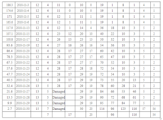
On the reduced factors between No.2300 no. 2299 steel rings, the displacement respectively is assessed. The measuring points are 1, 2, 3, 4, 5, 6m from the roadway surface. Surface convergence calculating points are established between No.2300 no. 2299 steel rings and cross syndication point method is used. Specific observation data are shown in Table 2.
DATA ANALYSES
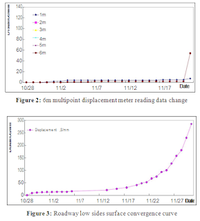
Physique 2 and Amount 3 show that roadway deformation and multipoint displacement reading data could be split into three stages, specifically, more than 120m, 120m~50m, significantly less than 50m from the working face. When the length is more than 120m, roadway surface convergence and multipoint displacement meter reading data signify little change. Within the length of 120m~50m, surface convergence data show a 93mm displacement occurs on low attributes, as the multipoint displacement meter reading data show that the displacement mainly occurs at the 4m measuring point, the total amount is 55mm, this means that fracture development looks within the length of 3~4m also. No reading data changes happen at the measuring points of 1m, 2m, 3m, 5m and 6m.
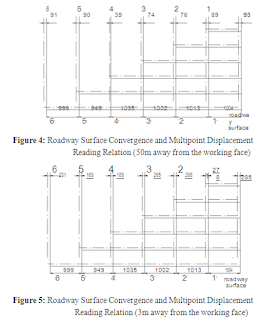
Predicated on the analyses of surface convergence and multipoint displacement data, roadway surface convergence and multipoint displacement reading relationship Figure at the website of 50m from the working face (Number 4) and roadway surface convergence and multipoint displacement reading relationship Figure at the website of 3m from the working face (Amount 5) are attracted. Based on the comparison of Amount 4 and Shape 5, we discovered that:
- Certain compression and fracture development areas can be found on roadways factors. The reading data of 5m and 6m measuring things show that compression occurs within the distances of both 50m~120m and 4m~6m from the working face. Roadway surface reveals a 93mm displacement, the successive reading data of multipoint displacement meter six measuring items are respectively: 2mm, 3mm, 54mm, 19mm, 4mm and 17mm. Taking the 93mm roadway convergence into consideration, these six measuring points move towards roadway inner spend the the distances of 89mm, 76mm, 74mm, 39mm, 90mm and 91mm separately. Thus it is mentioned that rock and roll on the factors wholly move towards roadway centre with a distance of 91mm within the length of 6m from the roadway surface.
- Within the length of 50m, the progress stress increase immediately ends in well-defined roadway deformation and the displacement on low attributes extends to 285mm. The successive reading data of multipoint displacement meter six measuring factors are respectively: 54mm, 116mm, 96mm, 20mm, 7mm and 17mm. Taking the 285mm roadway convergence into consideration, these six measuring points move towards roadway inner spend the the distances of 231mm, 169mm, 189mm, 265mm, 268mm and 278mm independently, namely, within the length of 6m from the roadway surface, rock and roll on the factors move towards roadway middle with a distance of 231mm overall.
- From roadway surface to interior rock, rock and roll mass show different dilatancy. Dilatancy occurs within the length of 1~5m, whereas compression occurs within the length of 5~6m.
- The deformation implies that measuring tips stress little by little enhances, roadway surface displacement and multipoint displacement meter reading data increase combined with the shortening of distance from working face. The assisting stress value made by roadway supporting composition is smaller than encircling rock and roll stress added value, thus the encompassing rock shows up fracture dilatancy and overall displacement within the length of 5m. Within the length of 120m~50m from the working face, fracture closes at the number of 4~6m area. Within the length of 50m, fracture closes at the number of 5~6m area and opens at the number of 4~5m area.
- The deformation demonstrates zoning fracture prevails during the encompassing rock and roll deformation process within the length of 5m from the roadway surface.
CONCLUSION
- Through the process of profound coal mining, certain fracture areas are present in the profound part of encompassing rock. This trend is greatly not the same as the encompassing rock and roll deformation rules of shallow part, which requires further review.
- Within the advance stress attentiveness area, roadway high- and-low edges surface convergence contains two parts: deformation triggered by roadway factors rock and roll fracture dilatancy and roadway attributes rock and roll overall displacement toward roadway centre.
- Weighed against shallow part, the profound roadway surrounding rock and roll overall displacement shows up an evident change, namely, encircling rock and roll surface shows a larger displacement, which reaches 300m approximately; while deep surrounding rock overall displacement has a larger occurrence range, it even occurs at the website of 6m.
ACKNOWLEDGEMENTS
I owe my deepest appreciation to Teacher Zhang Nong and Mr. Zheng Xigui, who offered me of valuable ideas plenty. Meanwhile,I'd like to thank the next schoolmates for a myriad of help they have got offered through the procedure for data collection : Chen Changyun, Liu Ningning, Liu Liming, Zhang Pengchong, Ma Zhenqian, amongst others.
REFERENCES
- Liu Xinguang, Gu Yingshi, Liu Tao. Isolated island working surface mining impact geostatie pressure monitor engineering research: The 2008 national symposium on rockburst and the Vol. 20 [2015], Bund. 2434 2008 of national coal mine safety, high efficiency, clean mining technology symposium[Z]. Jing de zhen:2008123-127.
- Lu Yan, Zou Xizheng, Cui Daopin, etc. Theoretical analysis and practice of fragmentation circle in surrounding rock[J].Journal of Liaoning Technical University (Natural Science Edition). 2007, 26(2): 219-221.
- He Fulian, Zou Xizheng, Qu Qun Di, etc.Mining roadway in soft rock unloading pressure engineering design and Practice[J]. Mining pressure and strata control.2002, 19(1): 40-42.
- Li Hui, Peng Gang, Peng Wenqing.Analysis for water-rush mechanism of roof's karst water for influence of fault activation[J]. Coal mine modernization. 2009, ""(4): 126-128.
- Chen Ke, Bai Jian-biao, HU Zhong-chao, Analysis of influence of advance abutment pressure on dip and rational end mining line selection[J]. Coalmining Technology.2010, 15(1): 35-37.
- Deng Zhigang.Study on coal permeability and gas mirgration law under high intensity mining in Lu An mining area[D].Coal Science And Technology.2007.
- DOU Feng-jin, TU Shi-hao, WU Qi.Stress concentration role mechanism of ultra thick seam to cause pressure bumping[J].Coal mine engineering.2009, (7): 75-78.
- FAN Shengqiang, ZOU Xiheng, Liu Guoliang. Distributing discipling of abutment pressure behind working face[J].Journal of H eilongjiang Institute of Science &Technology 2006, 16(2): 78-81.
- Fan Shibin. Near broken roof and nicking in fully mechanized mining face control technology[J]. Shandong coal science and technology.. 2006, (1): 2, 4.
- FAN Xiao-gang, Wang Hong-tu, HU Guo-zhong, Pressure-relief scope for the Exploiting of steep-inclined oblique under-protecting strata[J].Journal of China University of Mining & Technology.2010, 39(3): 380-385.


0 komentar: